2 Review PNG drafts and refine the model
PAGE 2 OF 3 • REVIEW
Use pictures to direct the next revision
You can supervise a model without knowing how to draw every surface yourself.
Read the drawing critically
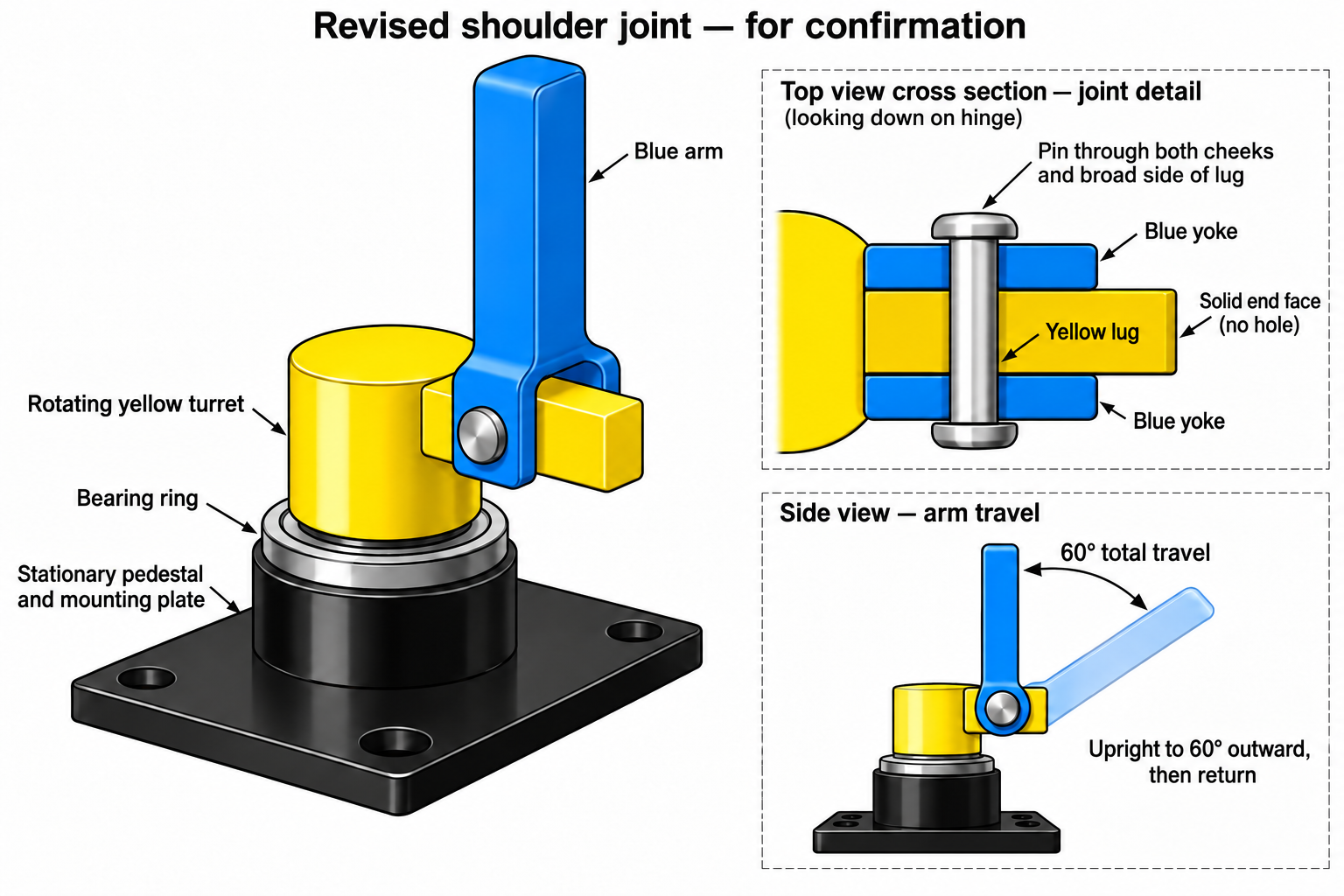
The shoulder joint gave us a useful lesson. A blue fork, or yoke, needed to straddle a yellow lug. The pivot pin had to pass through both blue cheeks and the broad side of the lug. An early illustration did not communicate that consistently.
Instead of asking ChatGPT to “improve the robot”, Johan pointed to the connection that needed correcting. Top and side views made the intended joint easier to explain.
A joint must work throughout its travel
Getting the pin direction right was not enough. The bridge of the blue fork also needed clearance as the arm moved. We asked for a raised bridge and a check through the proposed sweep.
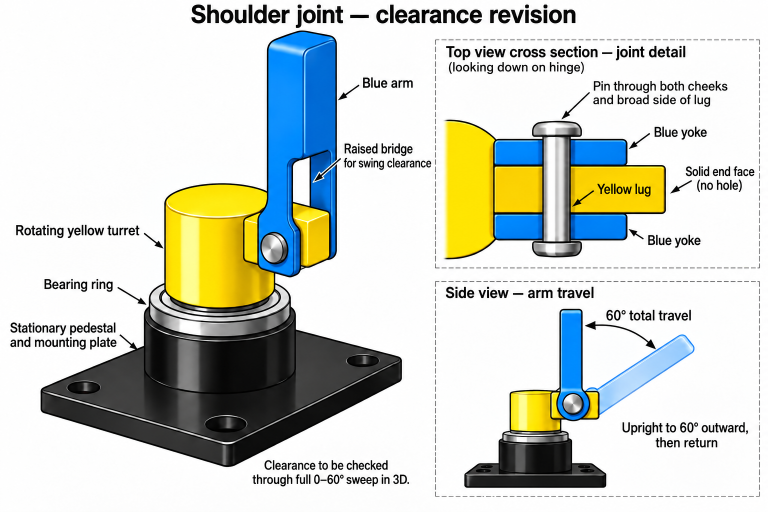
Notice the changing brief: the early concept shows 60° on each side of upright. The revised shoulder shows upright to 60° outward and back. Later animation requests extended the movement further. These are design iterations; use the latest agreed instruction rather than combining all the angles.
Give a correction that can be checked
Keep the stationary base and yellow turret unchanged. The blue fork must straddle the yellow lug. The pin must pass through both blue cheeks and the broad side of the lug, not its end face. Raise the bridge enough to clear the lug throughout the agreed arm movement. Show the revised top and side views before producing the next GLB.
For your own model, take a screenshot from the angle that reveals the problem. Add an arrow or circle and say what must change and what should stay the same. If front, side and top views disagree, resolve the disagreement before authoring the next version.
Specify the gripper sequence
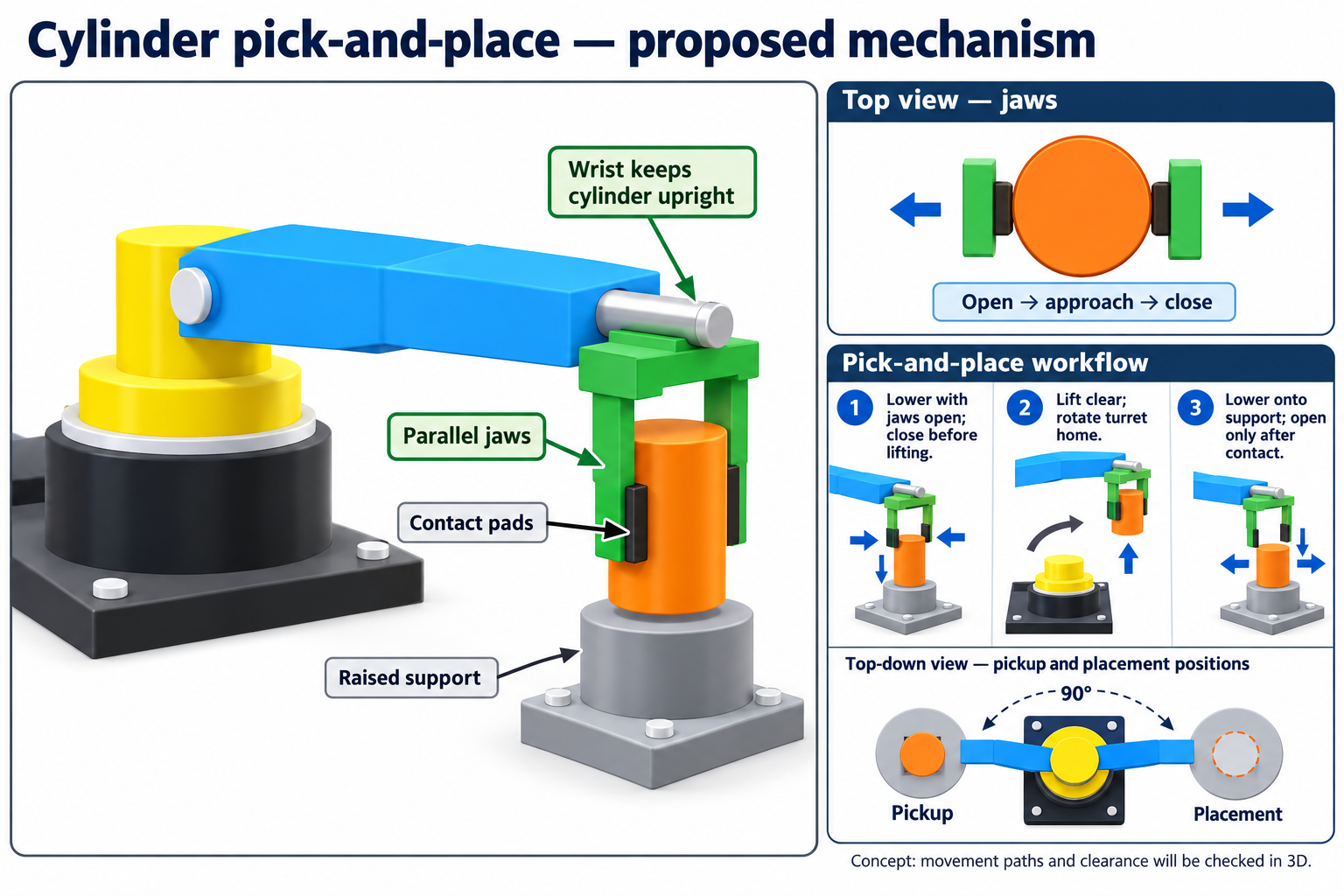
We asked for jaws that open to approach the cylinder, close while it is supported, lift it clear, carry it upright, lower it onto the other support, and open only after contact. The wrist had to compensate for arm movement so the cylinder stayed upright.
The useful review loop was: describe → inspect PNG → correct → generate GLB → test in PowerPoint. Repeat when the test reveals a new problem. A PNG is a discussion tool; the moving GLB is the test of the result.
Your review task
Inspect one of your own proposals. Identify a connection, a clearance and a movement that need checking. Write one correction with a clear acceptance condition, such as “the arm must not pass through the turret at any point”.
Check your understanding — Which result should you trust if the PNG and moving GLB disagree?
Inspect the actual GLB, compare it with the intended design, and request a correction. A persuasive PNG does not override an error in the model you will use.